MOSFET Selection for Drone Battery Charge-Discharge Management
MOSFET Selection for Drone Battery Charge-Discharge Management
Lithium-ion batteries used in drones have large capacities, often up to 6000mAh, to meet the demand for extended flight times. Inside the battery pack, power MOSFETs are typically connected in series between the battery and the output load, with a dedicated IC controlling the MOSFET’s switching to manage charging and discharging. Under normal conditions, the power MOSFET operates without issues. However, in extreme scenarios—such as a drone collision during flight—the battery may experience a massive current surge. When the IC detects an overcurrent, it requires a delay before initiating protective action. During this delay, the MOSFET operates in the linear region due to the high current, requiring it to withstand both high current and high voltage simultaneously. Proper MOSFET design and selection are critical to prevent damage, which could otherwise lead to the drone crashing.
Operating Characteristics of MOSFETs in Drone Battery Management
During high-current testing of a drone battery pack, the internal MOSFET’s operating waveform is shown in Figure 1. The MOSFET operates in the linear region during the shutdown process under high-current conditions.

Short-Circuit Test Waveform
Power MOSFETs have three operating regions:
-
Cutoff Region: No current flows.
-
Linear Region: The MOSFET operates with high voltage and current, allowing large currents to flow.
-
Fully On Region: The MOSFET is fully conductive with minimal voltage drop.
Theoretically, as unipolar devices, N-channel power MOSFETs conduct only electron current when fully on, with no hole current. In the fully on region, the drain-source voltage (VDS) is low, and the depletion layer disappears entirely. However, in the linear region, VDS is higher, and the depletion layer persists. This leads to the generation of electron-hole pairs in the epitaxial layer (EPI), with holes contributing to the current flow.
When operating in the linear region, significant hole current is generated, flowing through the MOSFET’s body region to the source (S) terminal. This can potentially trigger the parasitic bipolar transistor, posing a risk to the MOSFET. The challenges of operating in the linear region include:
-
High Internal Electric Field: Increases hole injection.
-
Reduced Effective Channel Width: Compared to the fully on region.
-
Lower Threshold Voltage (Vth) and Breakdown Voltage: Increases susceptibility to damage.
-
Localized Current Concentration: Low Vth causes current to concentrate in specific areas, forming hotspots. The negative temperature coefficient (NTC) exacerbates this issue.
In the linear region, high voltage bias reduces effective body charge due to the depletion layer. Higher operating voltages intensify the internal electric field, enhancing ionization and generating more electron-hole pairs, resulting in larger hole currents. If manufacturing inconsistencies exist, localized areas may reach critical electric field levels, causing stronger ionization, higher hole currents, and an increased risk of parasitic bipolar transistor activation.
Experimental Testing
To measure the linear region characteristics of power MOSFETs, a test circuit was designed using the latest-generation MOSFET from AOS: AONS32100, with an on-resistance of 0.55mOhm, a voltage rating of 25V, and a DFN5x6 package. The circuit and test waveform are shown in Figure 3, depicting the Safe Operating Area (SOA) test waveform for 10V/10ms. The circuit can be tailored to specific measurement conditions to better align with practical applications.

Linear Region Measurement Circuit

Linear Region Test Waveform
Failure Analysis
As shown in Figure 4, when the MOSFET is turned on, the on-resistance (RDS) transitions from the negative temperature coefficient (NTC) region (where RDS decreases with rising temperature) to the positive temperature coefficient (PTC) region (where RDS increases with temperature). In the NTC region, hotter cells have lower on-resistance, causing surrounding current to concentrate in these areas.
(a) Negative Temperature Coefficient Region
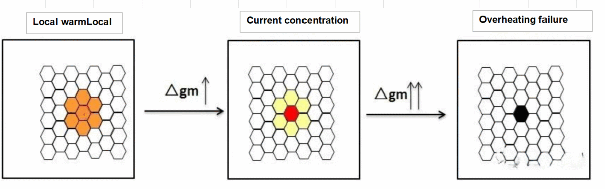
(b) Linear Region Failure Process

Negative Temperature Coefficient Region and Linear Region Failure of Power MOSFET
As current concentrates further, a positive feedback loop forms in the hotter region: lower on-resistance in a single cell leads to more current flow, generating more heat, which further raises the temperature and lowers the on-resistance. In the linear region, this positive feedback can lead to localized hotspots if the MOSFET remains in this region for an extended period. The current concentrates in a few high-temperature cells, causing their temperature to rise further and ultimately leading to thermal breakdown and device failure.
Improvement Methods
Optimizing the internal structure of the MOSFET can enhance its linear region performance. One approach is to increase the spacing between cells to prevent adjacent cells from heating each other and forming localized hotspots. While this may increase on-resistance, other methods can compensate, such as:
-
Using specific structures like superjunction P-pillars or deep trench field plates.
-
Modifying the electric field and current line distribution to reduce on-resistance.
The improved linear region performance of optimized power MOSFETs is shown in Figure 5. AOS’s next-generation MOSFETs not only exhibit superior linear region performance but also have lower on-resistance (RDS(ON)), providing an optimal solution for drone battery management applications.

Linear Region Performance and RDS(ON) Comparison
Conclusion
In drone battery management applications, power MOSFETs operate in the linear region during high-current shutdown processes, enduring high voltage and current stress. Selecting MOSFETs with excellent linear region characteristics is essential. Additionally, the system requires MOSFETs with low on-resistance to support high currents, minimize losses, and reduce heat generation. Optimized MOSFET designs, such as those from AOS, provide a robust solution for modern drone battery management systems.